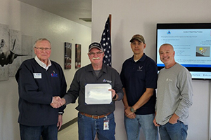
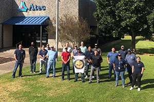
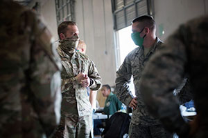
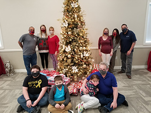
Support Solutions for Aerospace and Energy
281-276-2700
Connect with Us!   LinkedIn Twitter Facebook
Blog, Photos, News, Video

A Time for Celebration!

Today we celebrate Barbara Murray as she starts a new chapter in her life. Congratulations on retirement! She has been part of the Atec Team for 17 years and 3 days to be exact, and being exact and precise is something she has done for the company since she started with Atec back in the 90s. She has helped with our quality assurance, inspecting over 100,000+ items while at Atec that are now being used by our warfighters and customers in the field. Wow! We appreciate all that you have done and we will miss you Barbara.

Leave a Comment »

General Ben Robinson’s Journey and Focus on STEM Education


General Ben Robinson’s Journey from College Dropout to Air Force Pilot.  His story and realization along the way that  STEM education is needed to develop our future workforce.  Learn how the Aerospace Education and Industry Partnership (AEIP) is making this possible. Click here to read the article.

This article was provided to me by the Innovation Intake. To find out more information about STEM education visit Innovate+Educate. Use the STEM Directory to find an organization near you.

Leave a Comment »

CFD – The heart of aero systems engineering analysis

When engine test cells first came to the scene, air flow prediction was a guessing game. Sometimes designers made good guesses; sometimes they made bad guesses. Then Computational Fluid Dynamics (CFD), shedding some much needed light on the critical aero systems engineering analysis that always takes place when engineers design propeller and turbine engine test cells.

Background

During the early years of propeller and turbine engine test cell design, there was a great deal of iterative trial and error regarding test cell airflow dynamics.  Engine manufacturers and dedicated suppliers in the business developed rule of thumb designs to ensure that flowfield-related things like Cell Depression, Cell Pumping, Entrained Airflow and Section Velocities all met average aero systems engineering guidelines for the aerothermodynamics of mixed gas flow in a controlled volume.  Various approximations were used to predict the engine test cell flow performance for a particular engine.  The problem with the trial and error method was that it cost both time and money, for the supplier and the client.

Test Cell Aerodynamic Theology

Test cells typically do not fit the standard design practice for clean airflow that you find in a standard wind tunnel system.   Because of the need for very controlled laminar flow in a typical wind tunnel test section, the application of standard fluid flow aero systems engineering equations works well for wind tunnels; the designer keeps obstructions to an absolute minimum, ensuring that all transition zones reduce flow separation and turbulence as much as possible.

Test cells, however, are the antithesis of a wind tunnel.  They tend to have anything but a clean entrance to the test section, so using standard fluid flow equations from aero systems engineering practices model cell airflow dynamics.

Due to this fact, some designers turned to physical scale models using modified Bunsen burners as engine simulators in an attempt to avoid building a twenty million dollar albatross with airflow problems.  Still, these scale model systems were limited in successful airflow prediction even on their best day.

Hence, trial and error test cell designs led to that great engineering practice of rule of thumb.  In other words, we found a solution that worked over here, let’s scale it up or down and repeat the process.  However, as engine bypass ratios and mass airflows have continued to increase, and cost sensitivities on projects have become paramount, the trial and error rule of thumb method has presented obvious drawbacks.


A typical Atec CFD Airflow Model

CFD to the Rescue

Test cell design companies were instantly drawn to the science of Computational Fluid Dynamics for this very reason.  CFD allows an engineer to construct a model of a flow field, such as a wind tunnel or an engine test cell and then apply boundary and state conditions to its flow media. Similar to a wind tunnel, and engineer can then visualize pressure, temperature and velocity profiles within the flow field boundaries.   However in the early days of CFD, this high level of aero systems engineering analysis was reserved for massive computer systems at universities and research labs. Eventually, CFD made its way to computer systems that could be purchased by large corporations and finally to major players in the industry.

In the same way that computer aided design (CAD) has revolutionized drafting, CFD, coupled with computer aided engineering (CAE) tools with 3D modeling capabilities such as SolidWorks™, has revolutionized test cell aerothermodynamic performance prediction.

With the advent of PC Workstation CFD software bundled with industry-standard CAE tools, the ability of the test cell designer to visualize the potential issues in a test cell airflow management system has reached new plateaus.  CFD has become an essential tool in the aero systems engineering toolbox for test cell design teams.

Summary

There is still a definite need for engineers to do their due diligence by the tried and true calculation method for gross airflow performance.  However, the complex flow field of an engine test cell demands that the responsible engineer develop a full 3D model of the test cell complete with all obstructions in the flow field at all levels, to ensure the performance of the test cell to the best of their ability.

Of course, even the best of CFD models, should be examined against standard rule of thumb conventions to make sure the model falls in the range of expected performance.  There is rarely a need to reinvent the wheel when it comes to aero systems engineering design methods.

There is no substitute for good engineering practice.  All engineers must always remember that the computer software is just a tool, not the law, when it comes to designing a complex system such as a propeller or jet engine test cell.  The basic tenets of aero systems engineering, however, always apply.

Leave a Comment »

Turbine Engine Test Cell

Photo Credit: Tim Kern

The article The Small Turbine Engine Test Cell, written by Tim Kern, featured the test cells at the Rolls Royce Indianapolis facility. Atec was pleased to see our “green,” Phoenix  Modular Test Facilities displayed in the January 2012 edition of the Aircraft Maintenance Technology Magazine and on the AviationPros website.

Leave a Comment »

Delta and Atlas Launches from 2011

Pratt & Whitney Rocketdyne’s Video of the 2011 Delta and Atlas Launches!

Leave a Comment »

Engine Test Cell Challenges 2012 and Beyond

Engine Test Cells have been around for the aviation industry since the dawn of the industry.  The Wright Brothers performed extensive testing on their small piston engine to verify performance with their belt driven propeller system.  As mechanics, they understood not only that a motor is only as good as the parts and the people who put those parts together, but that a motor must be tested as a working system prior to installation.  Why is that, you ask?  Because once you’re in the air, the time for verifying performance is over.   Over 100 years after that historic flight at Kitty Hawk, the song remains the same, so to speak.  Whether an engine is being built for the first time or thousandth, it has to be tested for performance verification prior to flight.

As such, Engine Test Cells are a necessary evil.  The Test Cells are typically not a profit center, even for an MRO.  That being said, heaven help you if you don’t test an engine and your aircraft falls from the sky due to engine-related failure. Engine Test Cells—you can’t live with them, and you certainly can’t live without them!


Engine Test Cells generally fall into two categories at the highest level:

  • Research and Development Cells
  • Production and Overhaul Cells

These two types of cells met very different needs.  R&D Cells can be complicated and costly, but they allow the OEMs to develop new engine designs in an effort to beat out the competition for that valuable pylon space known as the engine mount on an aircraft.  Production and Overhaul Cells typically house “get-it-done” activities, where through-put and operational readiness is key to OEM and MROs alike.  Every client wants a Test Cell that is both versatile and low-cost. Although a Test Cell  rarely becomes a profit center for an operator, the benefits provided by the test cell far outweigh the costs.

Leave a Comment »

Production and Overhaul Test Cells outnumber R&D facilities by a large margin


In the old days, your test cell had an engine mount, a few gauges, a few hoses and cables, a start system, a fuel system and a pad of paper, and you were ready to fire up.  However, since the inception of powered flight, engine power and complexity have increased at an exponential rate, especially with the advent of the jet engine in the years after WWII, and then again with the introduction of digital controls.

Enter the economy.  The last few years have wreaked havoc with the aviation industry.  Rising fuel costs have made it even more expensive to operate aircraft.  Specific fuel consumption is now of paramount importance.  Flight readiness of an aircraft—whether for private fleets, military, corporate or commercial air operators—is critical.  If an aircraft is on the ground, it is not performing its mission or making money, plain and simple.   The economics of maintenance have come under increased scrutiny for both the military and commercial sectors.  “Give me the safest, most reliable engines you can for the least amount of money,” has become the standard for MRO.

Enter the environment.  By their nature, Engine Test Cells are not cut out to be nice, earth-friendly neighbors in the community.  No one ever wakes up and says “Gee, I hope we get a turbine engine test cell built next to us, because that would sure help our property values increase.”  Test Cells are smelly, dirty, noisy neighbors full of fuel, oil, and grease—commonly referred to as hydrocarbons—and they literally emit tons of combustion by-products into the air with every engine test.

Enter the FAA and OSHA.   Worldwide guidelines for aircraft safety and the health and safety of maintenance employees have also increased significantly over the past few decades.  Fire systems are rarely simple, hand-held extinguishers anymore, for example, but are fully automated release systems that automatically notify the fire department.  Fire retardant agents have become more expensive as the standard oxygen-depleting fire systems, like Halon, have been deemed environmentally unfriendly.   Control rooms have to allow the personnel inside to carry on conversations to protect users from hearing loss.  These are all good things, but they come with a price tag.

Let’s go back to the economics for a minute. As a test cell, being a good neighbor costs money—lots of it.  Acoustic treatments and environmental containment also drive a tremendous amount of cost into test cells.  As we are all aware, any noisy activity, be it a rock concert or a NASCAR race, is always compared to the noise of a jet engine.  Everyone is geared from birth to think of jet engines as the noisiest thing on the planet.  Test Cells have migrated from outdoor operations to indoor, fully acoustic isolated structures.  A new test cell to test the 100K+ thrust engines that power large commercial jet liners can now cost upwards of $40-50 million dollars.  Building construction and acoustical measures account for over half the cost. Depending on location, another 10-15% of cost can be wrapped up in environmental containment and safety issues.

Leave a Comment »

MROs must be both Technically and Business Savvy

Test Cells still have the same mission as they did with the Wright Brothers: verifying engine performance prior to flight.  How that mission gets accomplished however is very different  today.

On one hand, you could argue from a safety and operational readiness standpoint that test cells should be your most appreciated asset, but, on the other you could say that Test Cells are the single biggest sunk cost for an MRO; they are pure overhead and a pain in the neck to maintain.

So how does today’s Director of Maintenance balance their shop mission and engine test cell requirements, and incorporate all the latest gadgets to handle the ever increasing complexity of engines all on a slashed budget?  Terms like sunk costs, fixed assets, contribution, tooling charges, consumables, re-test, qualifications, etc., have turned the operation into a full-on business enterprise.

The challenges of Engine Test Cells for 2012 and beyond are balancing cost and schedule against capability, reliability and performance.  The days of “the sky’s the limit”are past.  Today’s MROs have to be both technically as well as business savvy.

*****

The purpose of this post area is to discuss the challenges posed by the Test Cells of today and tomorrow in both generalities and in specific details.  Please feel free to comment on our cover post or start your own thread regarding how you see the Challenges of Test Cells.

Leave a Comment »

2011 Rocket Launches

Photo Credit: Gene Blevins/LA Daily News

January 20, 2011 – Vandenberg Air Force Base – NROL 49
Atec’s 2011 launch schedule began with the maiden voyage of a Delta 4-Heavy rocket from California,  the largest booster ever flown from the West Coast. The RL-10 engine upper stage deployed a crucial and clandestine replacement satellite into a polar orbit for the National Reconnaissance Office’s sophisticated constellation. The Latin words “melior diabolus quem scies” are inscribed on the mission patch. This roughly translates to mean “the devil you know,” as in the phrase “better the devil you know than the devil you don’t know.” Launch the article.


March 5, 2011 – Cape Canaveral – USA 226 (X-37B)
The first Atlas 5 launch of 2011 inserted the Pentagon’s second experimental X-37B, America’s miniature military space shuttle, into Earth’s orbit to begin a secretive long-endurance mission. On November 29, 2011, a spokesperson for the Secretary of the Air Force announced the mission was extended beyond its original life expectancy, citing ongoing experimentation. See launch photos.


Photo credit: Justin Ray/Spaceflight Now

March 11, 2011 – Cape Canaveral – NROL 27
Fast on the heels of the Atlas launch, a medium-class Delta 4 lifted off from the cape with another NRO spacecraft headed for a geosynchronous orbit 22,300 miles above the earth.  This satellite will serve to relay data from low-altitude spacecraft such as imaging spy satellites. Read more about the mission and see photos.


Photo credit: Gene Blevins/LA Daily News

April 14, 2011 -  Vandenberg Air Force Base – NROL 34
Capping off six launches in seven months for the NRO, an Atlas 5 launched from the West Coast carrying a pair of formation-flying ocean surveillance spacecraft.
Details surrounding the purpose and final orbit of the satellite are classified, but the new spacecraft will definitely serve a role for the U.S. military. Read the full story and see photos.


Photo credit: Pat Corkery/ULA

May 7, 2011 – Cape Canaveral – SBIRS GEO-1
Atlas 5 continued to perform flawlessly in 2011, launching the long-awaited next generation in early-warning missile detection satellites. SBIRS GEO-1 is the first of four spacecraft slated to replace the Defense Support Program satellites and is primarily intended to provide enhanced strategic missile and theater ballistic missile warning capabilities. See additional photos.


July 16, 2011 – Cape Canaveral – GPS 2F2
Launching from Florida, a Delta 4 lofted the second of a 12-ship advanced constellation of GPS satellites. The first of the GPS IIF series was launched May 27, 2010. Each of the 12 are expected to have a 12-year life span. The GPS IIF series continues the tradition of combined civil and military global positioning system satellite coverage. This was the 50th successful launch of a GPS craft by the Delta family dating to 1989. Watch the launch.


August 5, 2011 – Cape Canaveral – Juno
Atlas 5 launched a NASA probe destined for Jupiter, 1.8 billion miles away from Earth. After launch, the rocket’s Centaur upper stage, powered by an RL-10 engine, carried out a first six-minute burn to boost the spacecraft into a temporary orbit. A second, nine-minute RL-10 firing 31 minutes later accelerated Juno to 25,000 mph, the interplanetary escape velocity. Three minutes later, the 4-ton spacecraft separated from the Centaur to fly on its own. Read NASA’s updates on the mission.


Photo credit: Justin Ray/Spaceflight Now

November 26, 2011 – Cape Canaveral – Curiosity
Ending Atec’s launch year, an Atlas 5 propelled a probe form Earth that carries the most advanced roving vehicle ever sent to the surface of another planet.  Destined for the Gale Crater on Mars, and carried by the Mars Science Laboratory, the car sized Curiosity will continue the work of previous Mars rovers in the search for life on our neighboring planet.  Interestingly, the RL-10- engined upper stage performed so flawlessly on this launch that Louis D’Amario of NASA’s Jet Propulsion Laboratory in Pasadena said, “This was among the most accurate interplanetary injections ever.” Read more about the precise launch, the postponement of the planned course adjustment , and NASA’s updates on the mission.

‎‎”Our only chance of long-term survival is not to remain lurking on planet Earth, but to spread out into space.”

— Stephen Hawking, interview in the Winnipeg Free Press, 19 November 2011.

Leave a Comment »

Record Year for Energy Services

2011 was a record year for our Energy Services group.  For that, our thanks go out to our loyal clients.

This past year demand in the field rose, and Atec jumped to the challenge by expediting orders so our customers could better serve their clients. Our continued team work with our customers in resolving obsolescence issues kept the orders flowing. Our hard work paid off, leading Atec to design and manufacture multiple cables for a new product released worldwide by a leading Houston-based customer, as well as to manufacture various surface measuring instruments, tools and spare parts for other Houston customers.

In 2012, we look forward to helping our customers achieve their goals and increase opportunities. If you are looking for a dedicated supplier with years of proven experience, give Atec a try for your 2012 requirements.

Leave a Comment »